 System types
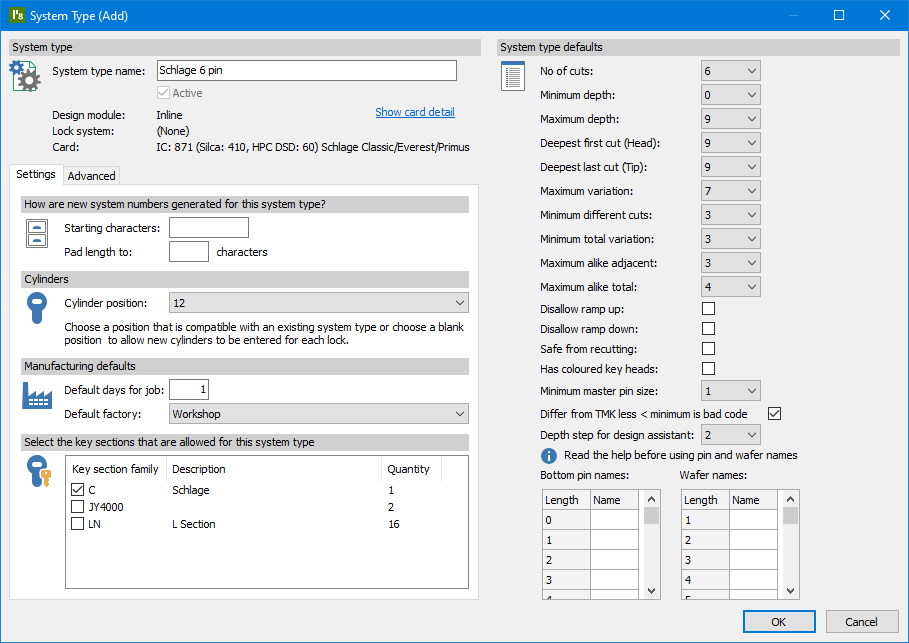
ProMaster Master-Keying 8 has 30 design modules to choose from that support a huge range of lock products. Each lock product will be preconfigured with default when making a new system. E.g. how many cuts the keys have, does the product use coloured heads, what the maximum difference between two adjacent cuts can be etc.
This leaves you with simple and clear choices when creating a new system.
 Data entry
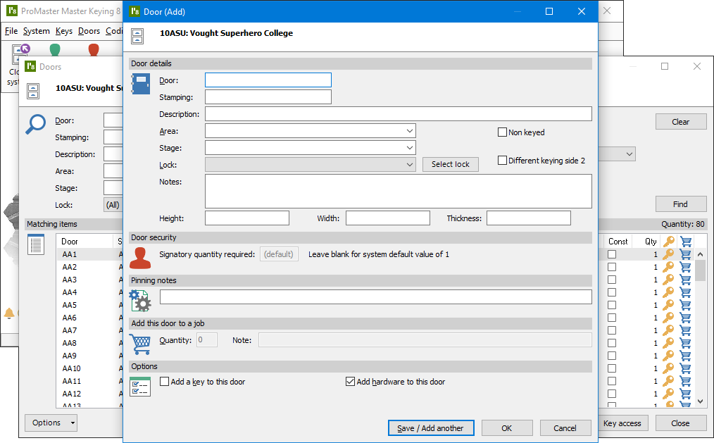
Quick, easy, and accurate to use. Data may be entered with various imports and duplication tools or manually. Even when manually entering data, ProMaster Master-Keying 8 expedites the process with predictive number sequence generation for appropriate fields (e.g. door and key numbers, stamping and descriptions).
 Coding
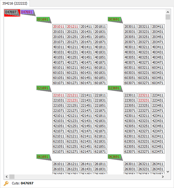
Coding, tree, matrix, grid
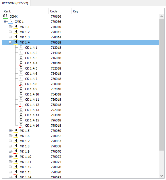
Whether you are familiar with ‘Code pages’, ‘Matrix’, ‘Grid’ or ‘Tree’, ProMaster Master-Keying 8 will display system codes in a familiar and usable format.
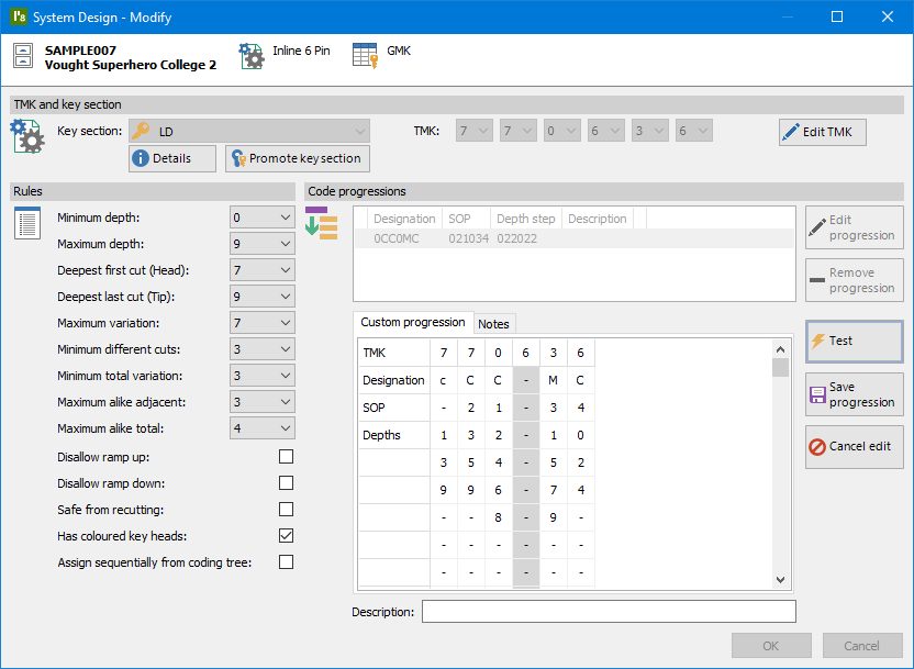
Code progressions let you present Matrix and Tree data multiple ways in the same system, even allowing a system to be viewed as both Tree-codes and Matrix-codes. See the complete progression or just a code page at a time. Kaba positional systems (e.g. experT pluS) use a sophisticated coding grid with a simple to use progression tool and give complete control over rotor-stators and over the assignment of blind cuts.
 Automatic coding
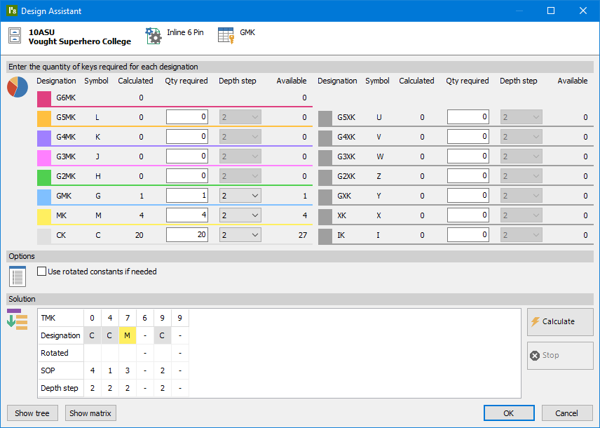
The design assistant calculates the design required for your system. Having designed a system, you are not locked in – you can alter the system design to allow for expansion or changes at any time. Powerful automatic coding capabilities do not compromise the ability for you to precisely control the system. In addition to automatic coding, you still have full control over codes and key sections.
 Jobs
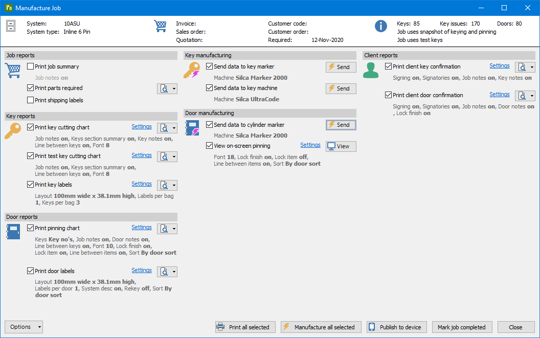
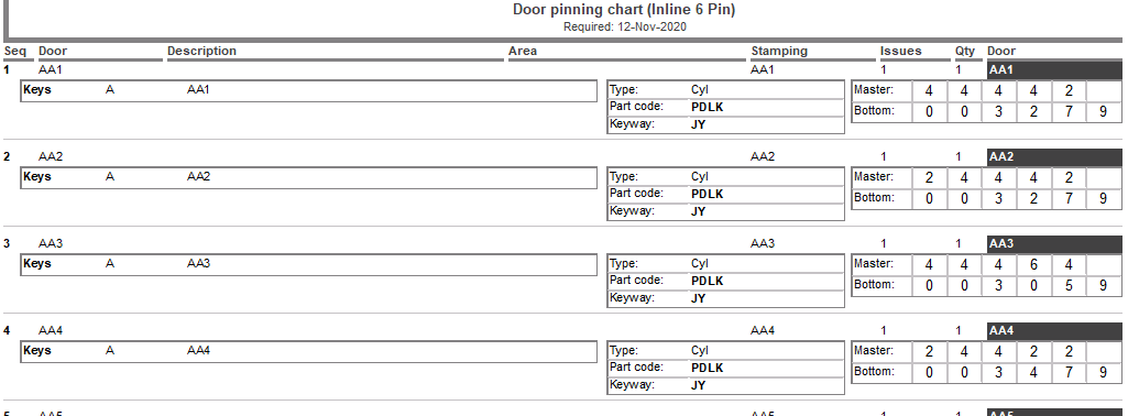
JobsJob manufacturing
ProMaster Master-Keying 8 generates job reports for parts required, key cutting, test key cutting, pinning (cylinder assembly) and client job summaries. On-screen pinning or publish to mobile app for cylinder assembly allow you to eliminate paperwork.
Manufacturing reports, on-screen pinning and exports are comprehensive, including all information required for manufacturing (such as bottom pins, master pins, top/driver pins, construction keying, part codes, cylinder keying, stamping, key cuts, coloured key heads and a whole lot more).
 Advanced
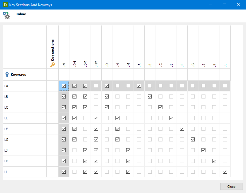
Multi key section/ keyway (Multiplex)
Complete control over key section families for you to enter your key sections, keyways, and their relationships.
Coding with flexibility
ProMaster Master-Keying 8 does not lock you into a design. All data is stored as the actual key cuts and calculations are performed according to the keys that operate each cylinder so even if you change the design you do not lose your data.
Multiple code progressions (key bit arrays) per system with progression sequence manipulation, progression notes, descriptions, rotated constants, and complete key bit array manipulation.